|
Altec Lansing 9846-8B Loudspeaker Bi-Amp Repair 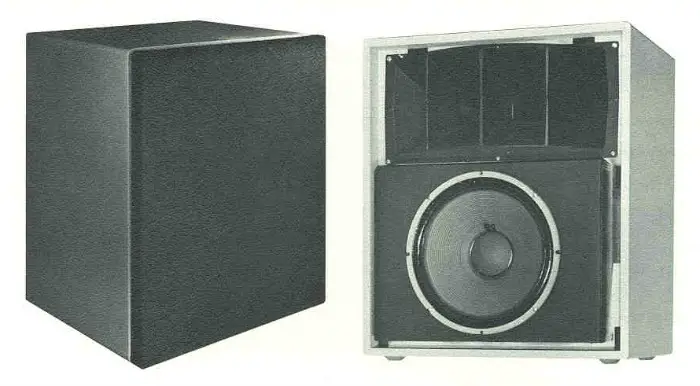 I purchased a pair of used Altec Lansing Model 9846-8B loudspeakers last year. They were made in the 1960s, so they are about 50 years old; old enough to be considered antiques. My goal is to restore them to original condition. The Altec 9846-8Bs come with built-in 771B solid-state bi-amplifiers. I assumed the built-in amplifiers would prevent kids from using the 9846s as a dummy load for their 1000 Watt car amps. The speakers squeal and motor-boat when the amps are turned on, so the horns, woofers and electronics were working. However, the amplifiers needed repair. The electronics worked, all the semiconductor parts in both amplifiers were okay. There were three electrolytic capacitors that needed replacing on the circuit boards of the two amplifiers (combined). There was another problem I had not anticipated, which was the result of an unfortunate parts selection by the manufacturer. They used a tin plated connector in a circuit that needed a gold plated connector. I repaired this by using a wire wrap gun to make new connection across the connector. With these repairs, both bi-amplifiers work like new. The picture below is a 771B amplifier with the back cover off. It has three circuit boards mounted across the back of the chassis. 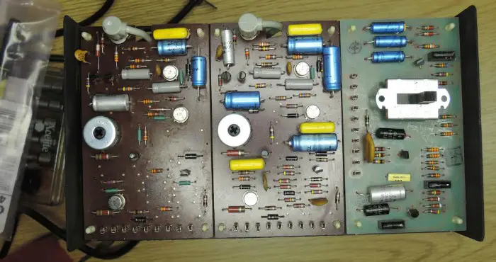 The function and repair issues of the three circuit boards from left to right are: 1. Left Circuit Board, 30-watt Amplifier for 500 Hz horn: The board has six axial leaded aluminum electrolytic capacitors that need to be checked and replaced as needed. I did not touch the potentiometer's adjustment. If you do not replace semiconductor parts, it should be okay. The board has a RCA Jack on its top end that is tin plated. The connector contacts are tight enough to be gas-tight, so there should not be contact oxidation to cause noise and popping. The row of nine tin plated connectors on the board's bottom end are connections to power transistors mounted on a heatsink off board. The open circuit voltage across the connections is high enough to cause them to self-clean tin oxidation. The power rail on this circuit board is about 60 volts. 2. Center Circuit Board, 60-watt Woofer Amplifier for 15 inch speaker: The board is the same as the one on its left, but has more parts. There are eight axil leaded aluminum electrolytic capacitors that need to be checked and replaced as needed. The description of the potentiometer and connectors on the left circuit board apply here. The power rail voltage on this circuit board is about 80 volts. 3. Right Circuit Board, Cross over Filters for Horn and Woofer amplifiers: The circuit board has six axial leaded aluminum electrolytic capacitors that need to be checked and replaced as needed. The three position slide switch in the middle of the board selects the cross over frequency of the high and low frequency filters. There are three metalized polystyrene capacitors on the circuit board. These set the filter frequencies and should not fail. The main cause of audio distortion and noise for the bi-amplifier is the row of 10 tin plated connections on the right side of this circuit board. The connections are not gas-tight and the open circuit voltage across the connections is not high enough for the connections to self-clean tin oxide, so they can fail. There would not be a problem if the connector and circuit board contacts where gold plated. The chassis side of the connector is nylon and will melt if soldered. I fixed the problem by wire rapping wires across the connection. Repair for the circuit boards was removing failed axial leaded aluminum electrolytic capacitors and soldering in new parts. Aluminum electrolytic capacitors use a wet electrolyte between their connecting plates. When the electrolyte dries, they stop working. You can replace all 20 electrolytic capacitors at once and not try to find individual bad parts. I used an LCR Meter (Inductance [L] Capacitance [C] Resistance [R]) with Kelvin connection (4 wires) to test the capacitors while soldered in the circuit. This type of meter measures capacitance or inductance, plus resistance at the same time. These meters can measure capacitors while connected in most circuits. Some Digital Volt Meters (DVMs) measure capacitance, but not accurately while connected in a circuit. If you repair your own bi-amplifiers, it is important to use replacement parts that fit into the same space as the part you removed. Use axial leaded parts, not radial leaded parts. These circuit boards do not have plated solder holes, so it is important that the replacement parts fit snugly to the circuit board surface. If they are loose, the 15 inch woofer will vibrate them and break the printed circuit on the underside of the circuit board. When you replace a part, note the location of the + or - markings. Electrolytic capacitors have polarity. If you install them backward, they will blow up. The old parts are barked with "+" for the positive end. New parts are marked with a "-" for the negative end. The circuit boards will work if you do not replace a positive end with a negative end. It is best to cut the leads of parts you are replacing on the top of the circuit board, then melt the solder on the bottom of the circuit board and shake the solder and old lead out of the mounting hole by tapping the circuit board on a table top. You are likely to need some solder wick to get all solder out of the mounting holes. Put the leads of the new part into the mounting holes and be sure the leads have adequate clearance. It they bind, you will rip the etched circuit of the bottom the circuit board. Tin plated connectors do not work everywhere. Tin conducts electricity until the it oxidizes. Tin oxide does not conduct electricity. Some tin plated connectors work reliably, because they are gas-tight and oxygen does not get into the electrical connection. This is the case for the RCA jacks on the top ends of the amplifier circuit boards. Applications that use tin plated connects work if the open circuit voltage across the connector is higher than 10 volts, or the current is higher than 10mA. Tin plated connectors with more than 10 volts open circuit across the connection are self-cleaning. Tin oxide is thin and the electric field breaks through it. An example is the automobile industry, which had problems keeping car starters working with six volt batteries, so they switched to 12 volt batteries in the late 1950s. The picture below shows the wires I wrapped. The black wires are grounds. The yellow wires are the inputs from the phone jacks on the front side of the amplifier and outputs of the cross-over filters for base and treble. The white wire is the 24 volt rail that powers the circuit board. The pins you are wire wrapping are 0.060 inch wide, use a part number WB26M wire rap bit and a part number P2224 sleeve on your wire wrap gun. Use 26 AWG wire. Strip about 1-1/2 inch of a 2-1/2 inch piece of wire, then 1/8 inch of the other end. I had not used wire wrap tools in a long time, so I kept trying wraps until I got good ones. If the wrap goes bad, you can wind the wire of the pin and try again. The part numbers are from an OK Industries Wire Wrap Tool Catalog. 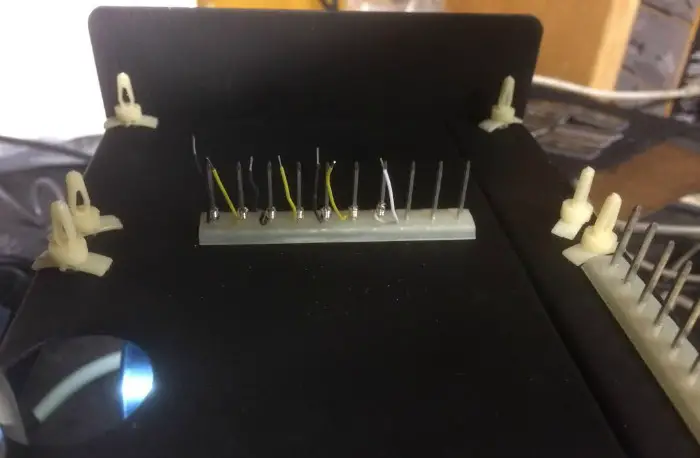 After wrapping the wires, tin the 1/8 inch stripped end with some solder. I tined the top side the circuit board contacts, not the part that connects the pins I had just rapped, with fresh solder. In some places rosin core solder would not stick, so I sparingly used acid solder paste to make a fresh tined spot. 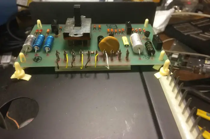 Place the repaired cross-over filter circuit board over its connectors and install it into the nylon clips. Solder the wires to the spots you tined on the circuit board contacts. The picture immediately above shows the finished job. |